HD44780 Character LCD Display
Character-based LCD display with HD44780 controller
🚀 Used in Projects (1)
📐 See This Display in Action
This display is featured in our interactive size comparison.
Overview
The HD44780 is a character-based LCD display controller that has become the de facto standard for simple text displays. These displays show individual characters in a fixed grid pattern (not pixel-addressable) and are commonly available in various sizes such as 16x2, 20x4, and 8x2 configurations.
Not sure how accurate it is that it’s de facto standard in 2025, but it has been for decades.
Probably more accurate name for my LCD is 1602A, HD44780 is just a generic name for the controller chip that’s compatible with HD44780 I suppose
My display is salvaged from an old device.
Display features:
- Character-based display (not pixel-addressable)
- Common sizes: 16x2 (mine 1602A), 20x4, 8x2, 20x2, 40x2
- HD44780 or compatible controller chip
- Multiple character sets available
- HD44780UA00 English-Japanese is my version
it.print("\xAF");printsツkatakana character
- 8 user-definable custom characters
- Built-in backlight (usually blue or green (mine))
- Operating voltage: 5V but it’s complicated
- Adjustable contrast via potentiometer but it’s complicated
Configuration Notes
There are two flavours of connecting the LCD display: lcd_gpio which is for parallel connection,and lcd_pcf8574 which is using PCF8574 I2C expander.
⚠️NOTE: If you are going to use backlight make sure you add current limiting resistor.
Using 5V Supply
☠️⚠️ DANGER: LCD needs 5V for VCC. Our ESP MCUs are not 5V tolerant so if you try to read from the LCD while connected to 5V you’ll fry your board! ALWAYS connect R/W to the ground!
The display is 3.3V compatible … but this is for logic. Unfortunately it requires to somehow craft at least 4V between VCC and V0 for it to be able to display anything. So, options are:
- use 5V for power and use a level shifter
- the reason for this is that minimum level for high signal is 70% of VCC which is 3.5V and that’s outside of our 3.3V output level.
- use 3.3V for power and somehow get extra -1V or so 👀
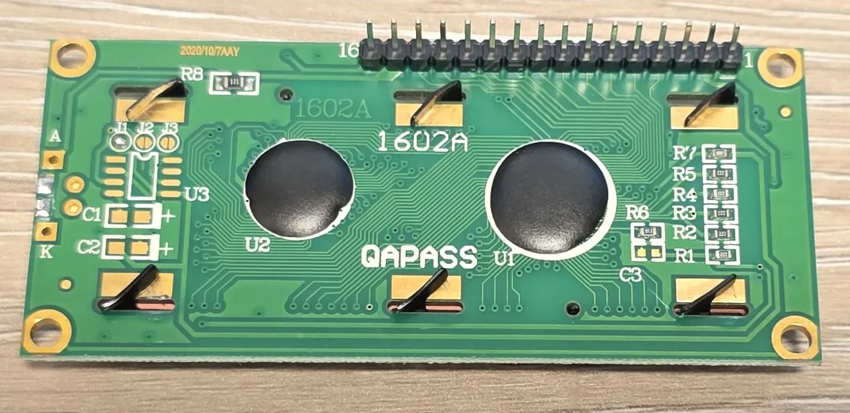
- this can be done with a charge pump, and there is even a placeholder for it on the back side
- hack something yourself … careful with this … see my notes below
For this I did “hack” something myself. I added a diode (1N4001 or 1N4148 will work) between 5V and VDD of the display. This gives me nearly no control of the contrast but it drops VCC enough that 0.7*VCC is around 3V.
I connected back light led to 5V and a resistor to limit current, that does not go through the diode.
NOTE: Since LCD consumes <10mA it should be safe to use even a signal diode like 1N4148 which can sustain 300mA continuous current.
Contrast
Contrast control can be achieved by adding a potentiometer between V0 and ground. I’m connecting it to the GND since I don’t have much headroom with my setup.
Backlight
Options:
- Connect A to 5V and K to 470ohm resistor to GND. This way I find it quite bright and no brightness control. You could use potentiometer, or
- It is possible to control brightness using ESP32 LEDC output or 8266 PWM output components and monochromatic light. I used D3 to control it, see the power wiring
Wiring 5V Power
Here is how I ended up wiring just the power part, and pins that require to be grounded (RW). D3 controls the brightness of the backlight, resistor is for current limit - it is 470ohm (you can choose different value - probably anything from 100 to 1K ohm will work just fine). I’m powering the display through 1N4148 diode which will give me enough voltage drop so 3.3V logic level will work just fine.

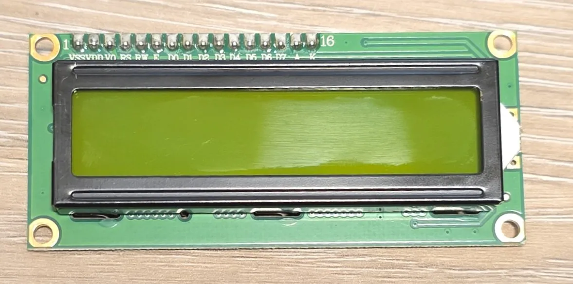
Pinout and Wiring
For GPIO Examples, I’ll be using 4-bit mode.
| Pin | Name | Description | D1 Mini | Notes |
|---|---|---|---|---|
| 01 | VSS | Ground | G | GND |
| 02 | VCC | +5V Power Supply | 5V -> | With a diode. See NOTE above |
| 03 | V0 | Contrast Adjustment | G | GND |
| 04 | RS | Register Select | D2 | Data/Command selection |
| 05 | R/W | Read/Write | G | GND (🚨 Always Write only mode) |
| 06 | E | Enable | D1 | ”Clock” signal |
| 07 | D0 | Data Bit 0 | NC | |
| 08 | D1 | Data Bit 1 | NC | |
| 09 | D2 | Data Bit 2 | NC | |
| 10 | D3 | Data Bit 3 | NC | |
| 11 | D4 | Data Bit 4 | D8 | GPIO |
| 12 | D5 | Data Bit 5 | D7 | GPIO |
| 13 | D6 | Data Bit 6 | D6 | GPIO |
| 14 | D7 | Data Bit 7 | D5 | GPIO |
| 15 | A | Backlight Anode | D3 | Positive connection: 5V |
| 16 | K | Backlight Kathode | G -> | Negative connection: resistor to GND |
NOTE: The documentation says either lower 4 or upper 4 bits can be used, but for me, it only worked connecting to upper 4 bits (4-7)
LCD GPIO
This one can be configured to use 4 pins (4-bit mode) of the data bus or all 8 pins (8-bit mode). For all GPIO examples I’ll use 4 bits.
For the examples I’ll be using D1 Mini, and will wire it up like this:
esphome:
  name: my-char-lcd

esp8266:
  board: d1_mini

logger:

substitutions:
  pin_enable: D1
  pin_rs: D2
  pin_data0: D8
  pin_data1: D7
  pin_data2: D6
pin_data3: D5NOTE: In the configuration above I used GPIO numbers as per D1 Mini board. If you specify the board for your platform, you should usually be able to use pin names from the board instead of MCUs GPIO numbers.
Full Wiring Diagram
Full wiring diagram for D1 Mini and 1602 LCD with backlight control.

Basic Configuration
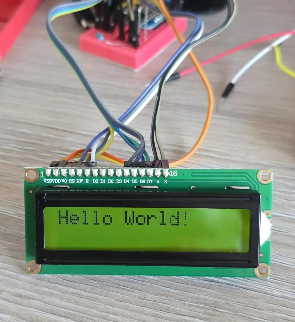
Basic configuration without backlight control (I actually had backlight disconnected for this picture).
# Example configuration entry
display:
  - platform: lcd_gpio
    dimensions: 16x2
    data_pins:
      - ${pin_data0}
      - ${pin_data1}
      - ${pin_data2}
      - ${pin_data3}
    enable_pin: ${pin_enable}
    rs_pin: ${pin_rs}
    #optional but don't use it
    #rw_pin: ...
    lambda: |-
      it.print("Hello World!");
With Backlight Control
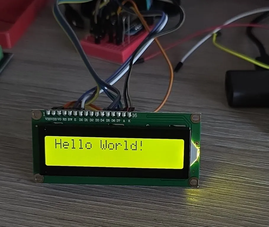
Basic configuration with backlight control.
esphome:
  name: my-text-lcd

esp8266:
  board: d1_mini

api:
  encryption:
    key: !secret my_text_lcd_api

ota:
  - platform: esphome
    password: !secret my_text_lcd_ota

wifi:
  ssid: !secret wifi_ssid
  password: !secret wifi_password


logger:

substitutions:
  pin_enable: D1
  pin_rs: D2
  pin_data4: D8
  pin_data5: D7
  pin_data6: D6
  pin_data7: D5

# Example configuration entry
display:
  - platform: lcd_gpio
    dimensions: 16x2
    data_pins:
      - ${pin_data4}
      - ${pin_data5}
      - ${pin_data6}
      - ${pin_data7}
    enable_pin: ${pin_enable}
    rs_pin: ${pin_rs}
    #optional
    #rw_pin: ${pin_rw}
    lambda: |-
      it.print("Hello World!");

output:
  - platform: esp8266_pwm
    pin: D3
    frequency: 1000 Hz
    id: pwm_output

light:
  - platform: monochromatic
    output: pwm_output
    #it will appear in home assistant
    name: "Backlight"
Using ESP32
When using EPS32 use LEDC component:
output:
  - platform: ledc
    pin: ${bl_pin}
    frequency: 1220 Hz
    id: pwm_output
TIP 💡: I used 1220 Hz for frequency - as per recommended frequencies. When I used 1000Hz I was getting flickering.
Other Images
1602a back: