ESP32 DevKit V1
Popular ESP32 development board with built-in WiFi and Bluetooth
Connection Types
🔲 See This Board in Action
This board is featured in our interactive size comparison.
Overview
Based on the ESP32-WROOM-32/ESP32-WROOM-32D module with built-in WiFi and Bluetooth capabilities. Has built-in antenna.
Additonal Hardware features
- Boot & Reset buttons - Boot button can be used, inverted on GPIO00
- LED on GPIO02
Test Status
- ✅ Basic Config + Internal LED & Boot Button
- ✅ GPIO - output: Internal LED, input: Boot Button
- UART
- SPI
- I2C
- I2S
- (LED) PWM
- IR
- ADC
- Touch Sensor
- DAC
- SD Card
Basic Configuration
Basic configuration with built in button and LED.
esphome:
  name: my-esp32dev

esp32:
  board: esp32dev
  framework:
#    type: arduino
    type: esp-idf

logger:

substitutions:
  boot_btn_pin: GPIO00
  builtin_led_pin: GPIO02

output:
  - platform: gpio
    pin: ${builtin_led_pin}
    id: builtin_led

light:
  - platform: binary
    name: "Built in LED"
    output: builtin_led

binary_sensor:
  - platform: gpio
    pin:
      number: ${boot_btn_pin}
      inverted: true
    id: boot_btn
    on_press:
      then:
        - output.turn_on: builtin_led
    on_release:
      then:
        - output.turn_off: builtin_led
Additional Notes
I’m using substitutions so I can re-use this example with other boards. I’m using this example as starting point for everything. Logging section added since any time I’m doing something new, logging is needed 🙂
HW-463 Variant
- USB-to-UART: CP2102
- Module: ESP32-WROOM-32
- CPU: ESP32 (ESP32-D0WDQ6 - Dual Core)
- USB: Micro-USB
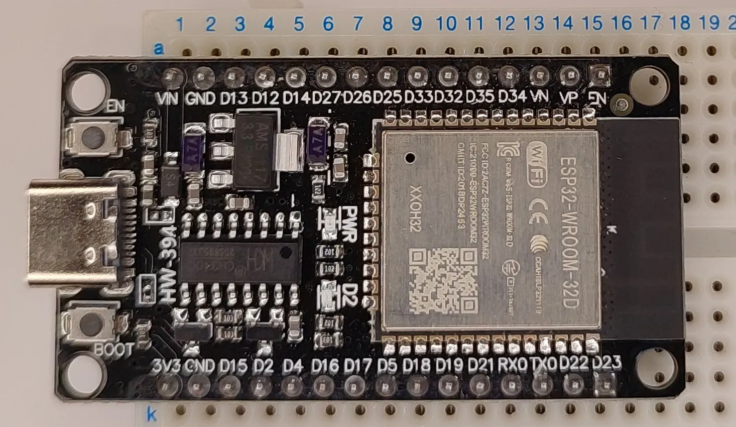
HW-394 Variant
- USB-to-UART: CH340G
- Module: ESP32-WROOM-32D - newer and slightly better than ESP32-WROOM-32
- CPU: ESP32 (ESP32-D0WD - Dual Core)
- USB: USB-C
Module Specifications
- Module: ESP32-WROOM-32
- CPU: Xtensa dual-core 32-bit LX6 CPU, frequency up to 240MHz
- RAM: 520KB SRAM (320KB usable)
- Flash: 4MB
- WiFi: 802.11 b/g/n
- Bluetooth: v4.2 BR/EDR and BLE
- Operating Voltage: 3.3V
- Input Voltage: 5V (via USB or VIN)
- GPIO Pins: Up to 32
- 5 strapping GPIOs
- 6 GPIOs need for flash/PSRAM
- ADC: 2*12-bit ADC (up to 18 channels)
- PWM: 16 channels
- I2C: 2 interfaces
- I2S: 2 interfaces
- SPI: 4 interfaces
- UART: 3 interfaces
Board Pinout
The ESP32 DevKit V1 has 30 pins in total:
Power Pins
- 3.3V - 3.3V output (AMS1117 3.3)
- GND - Ground pins (x2)
- VIN - Input voltage (5-12V) or 5V output from USB (when powered via USB)
- EN - Enable pin (reset when pulled low)
GPIO Pins
- GPIO0-GPIO39 - General purpose I/O
- GPIO34-39 are input-only
- GPIO6-11 are connected to flash (don’t use)
- Some pins have boot mode constraints (GPIO0, GPIO2, GPIO12, GPIO15)
Special Function Pins
Check out ESP32 datasheet IO_MUX table for which pins can be used for what because a lot of them are multiplexed.
- Touch Sensors: GPIO0, GPIO2, GPIO4, GPIO12-15, GPIO27, GPIO32-33
- I2C: By default GPIO21=SDA, GPIO22=SCL
- SPI: By default GPIO23=MOSI, GPIO19=MISO, GPIO18=SCK, GPIO05=CS
- DAC: Dual 8-bit DAC outputs: GPIO25 and GPIO26
- Analog & Touch: see pinout, many GPIOs can be used as ADC1 and ADC2 input, capacitive-touch sensors and LED/Motor PWM signals
Other interfaces: SD card, UART, SDIO, I2C, I2S, IR, pulse counter, CAN
Important Notes
⚠️ Boot Mode Pins: Be careful with GPIO0, GPIO2, GPIO12, and GPIO15 during boot. These affect boot mode selection.
⚠️ Input-Only Pins: GPIO34-39 can only be used as inputs and don’t have internal pull-up/pull-down resistors.
⚠️ ADC2 Limitation: Some ADC2 pins cannot be used when WiFi is active.
⚠️ Strapping Pins: Some pins are used during boot and may cause issues if connected to certain peripherals.
Troubleshooting
Board won’t flash:
- Hold the BOOT button while connecting USB (I had this issue with CP2102 variant, I had to hold BOOT button)
- Try a different USB cable (must support data)
- Check that CH340/CP2102 drivers are installed
Random resets:
- Check power supply (needs stable 5V, 500mA+)
- Add capacitors near power pins if using long wires
- Avoid connecting high-current devices directly
Other Images
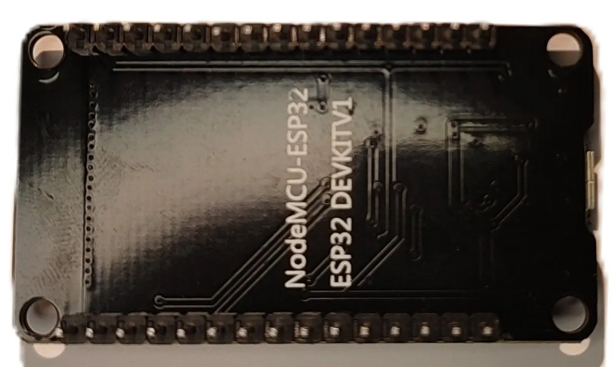
HW-463 version:

HW-463 version - back: