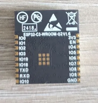
ESP32-C3-WROOM-02
ESP32-C3 RISC-V module with WiFi and Bluetooth LE
Connection Types
🔲 See This Board in Action
This board is featured in our interactive size comparison.
Overview
The ESP32-C3-WROOM-02 is a general-purpose WiFi and Bluetooth LE module based on the ESP32-C3 SoC. It features a 32-bit RISC-V single-core processor and is designed for low-power IoT applications.
Test Status
- How to use Hardware? 👀
- Basic Config
- GPIO
- UART
- SPI
- I2C
- I2S
- (LED) PWM
- IR
- ADC
- Temperature Sensor
- Bluetooth
- CAN?
Hardware Features
- Module: ESP32-C3-WROOM-02
- CPU: 32-bit RISC-V single-core processor, up to 160 MHz
- ROM: 384 KB
- SRAM: 400 KB (16 KB for cache)
- RTC SRAM: 8 KB
- Flash: 4 MB
- WiFi: 802.11 b/g/n (2.4 GHz)
- Bluetooth: BLE 5.0
- GPIO Pins: Up to 15 GPIOs available
- 3 strapping GPIOs
- ADC: SAR ADC (multiple channels)
- PWM: LED PWM controller
- SPI: Multiple interfaces
- UART: Multiple interfaces
- I2C: Hardware I2C
- I2S: Interface available
- USB: USB Serial/JTAG controller (built-in USB support)
- Other Peripherals:
- Remote control peripheral
- General DMA controller
- TWAI® controller (compatible with ISO 11898-1, CAN Specification 2.0)
- Temperature sensor
- General-purpose timers
- Watchdog timers
- Operating Voltage: 3.0V to 3.6V
Module Specifications
The ESP32-C3-WROOM-02 is a module that integrates:
- ESP32-C3 SoC
- 4 MB SPI flash
- PCB antenna
- All necessary passive components
NOTE: ⚠️ This module is designed to be soldered onto a carrier board for complete functionality.
GPIO Capabilities
The ESP32-C3 provides up to 15 GPIOs with various functions:
- Digital I/O: All GPIOs can be used for digital input/output
- ADC: Multiple channels for analog input
- PWM: Most GPIOs support PWM output
- I2C: Any GPIO can be configured for I2C (hardware support)
- SPI: Multiple SPI interfaces available
- UART: Multiple UART interfaces
- USB: Built-in USB Serial/JTAG (GPIO18/GPIO19)
Strapping Pins
The ESP32-C3 has 3 strapping pins that determine boot mode:
- GPIO2 - Boot mode strapping
- GPIO8 - Boot mode strapping
- GPIO9 - Boot mode strapping
These pins should be handled carefully during boot to ensure proper operation.
Basic Configuration
Basic configuration for ESP32-C3-WROOM-02 module.
esphome:
  name: my-esp32c3

esp32:
  board: esp32-c3-devkitm-1
  variant: esp32c3
  framework:
    type: esp-idf
USB Serial/JTAG
The ESP32-C3 includes a built-in USB Serial/JTAG controller on GPIO18 and GPIO19, allowing:
- Programming via USB without external USB-to-UART chip
- Serial communication over USB
- JTAG debugging over USB
This makes development easier and reduces the need for external components.
Important Notes
⚠️ Strapping Pins: GPIO2, GPIO8, and GPIO9 are used during boot for mode selection. Avoid connecting devices that could interfere with boot.
⚠️ RISC-V Architecture: The ESP32-C3 uses RISC-V architecture instead of Xtensa.
⚠️ Module vs Development Board: This is a module that requires a carrier board with:
- 3.3V power regulation
- USB connector (if using USB Serial/JTAG)
- Reset and boot buttons (recommended)
- Additional circuitry as needed
⚠️ Single Core: Unlike ESP32 (dual-core), the ESP32-C3 has a single core.
⚠️ Power Consumption: While optimized for low power, peak current during WiFi/BLE transmission can reach 350mA. Ensure adequate power supply.
Development Boards
Many development boards use the ESP32-C3-WROOM-02 module, such as:
- ESP32-C3-DevKitM-1
- ESP32-C3-DevKitC-02
- Various third-party boards
These boards add:
- USB-C connector
- Voltage regulator
- Boot and reset buttons
- LED indicators
- Breadboard-friendly pinout
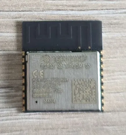
Other Photos
Back of the module: