ESP-01S
Minimal ESP8266 WiFi module with basic GPIO
🔲 See This Board in Action
This board is featured in our interactive size comparison.
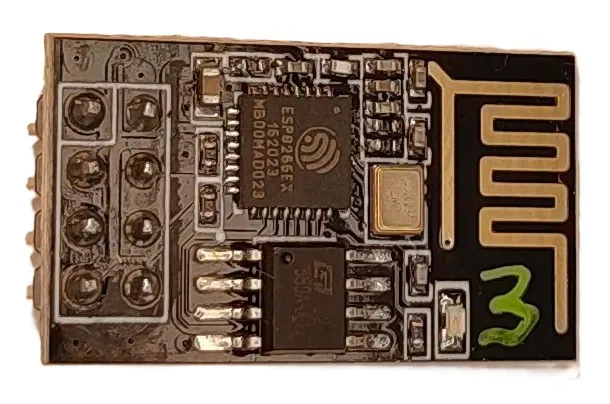
Overview
The ESP-01S is a bare-bones ESP8266 WiFi module with minimal hardware. It’s one of the smallest and cheapest ESP8266 modules available but requires external components for programming and operation.
Test Status
- 🧪 Basic Config + Internal LED
- GPIO
- UART
- SPI
- I2C
- I2S
- PWM
- IR
- ADC
Hardware Features
- Module: ESP-01S
- CPU: ESP8266EX single-core, 80MHz
- RAM: 80KB
- Flash: 1MB (typically)
- My board: GT25Q80A 8Mbit SPI Nor Flash
- Chip Marking: 580A-UGLI
- GPIO Pins: 4 available (2 easily accessible)
- WiFi: 802.11 b/g/n
- SPI: Hardware SPI
- I2C: Software-implemented
- I2S: Interfaces with DMA
- UART: 1 interface
- Operating Voltage: 3.3V
Additional Hardware Features
- Built-in LED on GPIO01
- No built-in USB-to-UART (requires external programmer with CH340G or similar)
- No built-in voltage regulator (requires external 3.3V LDO)
- No reset or boot buttons
- As bare bones as it gets
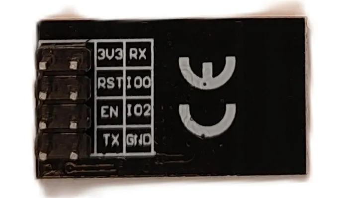
Board Pinout
The ESP-01S has 8 pins total:
Power Pins
- 3V3 - 3.3V input (requires stable, regulated 3.3V)
- GND - Ground
GPIO Pins
- GPIO0 - General purpose I/O, boot mode selection (pulled HIGH for normal boot, LOW for programming)
- GPIO2 - General purpose I/O, boot mode pin (must be HIGH during boot)
- TX - GPIO1, UART TX
- RX - GPIO3, UART RX
- RST - Reset pin (active LOW)
- CH_PD - Chip enable (must be HIGH for operation)
Basic Configuration
Basic configuration for ESP-01S with 1MB flash.
esphome:
  name: my-esp01s

esp8266:
  board: esp01_1m

output:
  - platform: gpio
    pin: GPIO01
    id: builtin_led

light:
  - platform: binary
    name: "Built in LED"
    output: builtin_led
Programming Setup
The ESP-01S requires an external USB-to-UART adapter for programming:
-
Connect USB-to-UART adapter:
- Adapter TX → ESP-01S RX
- Adapter RX → ESP-01S TX
- Adapter 3.3V → ESP-01S 3V3 and CH_PD
- Adapter GND → ESP-01S GND
-
Enter programming mode:
- Connect GPIO0 to GND
- Power cycle or pull RST to GND briefly
- GPIO0 can be disconnected after entering programming mode
-
Normal operation:
- GPIO0 should be HIGH (or floating with pull-up)
- CH_PD must be HIGH
- RST should be HIGH (or floating with pull-up)
Important Notes
⚠️ Power Requirements:
- Must use a stable 3.3V power supply
- Can draw up to 300mA during WiFi transmission
- Some USB-to-UART adapters cannot supply enough current - use external LDO for operation
⚠️ Boot Mode Pins:
- GPIO0 must be HIGH during normal boot, LOW for programming mode
- GPIO2 must be HIGH during boot
- Both should have pull-up resistors
⚠️ Limited GPIOs: With only 2 easily accessible GPIOs (GPIO0 and GPIO2), this module is best suited for simple WiFi-to-serial applications.
⚠️ No Built-in Protection: No reverse polarity protection, overvoltage protection, or current limiting. Handle with care.
⚠️ I2C: I2C is implemented in software, so any GPIO can be used, but GPIO5 and GPIO4 are the default pins. They are not available on the board, so if used, SDA and SCL pins need to be specified.
Use Cases
The ESP-01S is ideal for:
- WiFi-to-serial bridges
- Simple WiFi sensors with minimal GPIO requirements
- Retrofit WiFi connectivity to existing devices
- Projects where size is critical
Not recommended for:
- Projects requiring many GPIO pins
- Beginners (consider D1 Mini or ESP32 DevKit instead)
- Applications requiring easy reprogramming
Troubleshooting
Cannot enter programming mode:
- Ensure GPIO0 is connected to GND before powering on
- Check that CH_PD is HIGH
- Verify 3.3V power supply is stable
Module doesn’t boot:
- Check that GPIO0 and GPIO2 are HIGH (or floating with pull-ups)
- Verify CH_PD is connected to 3.3V
- Ensure power supply can handle current spikes (300mA+)
Random resets or crashes:
- Almost always a power supply issue
- Add 100µF capacitor near 3.3V pin
- Use proper 3.3V regulator rated for 500mA+
Other Images
Back of the module:
With the adapter:
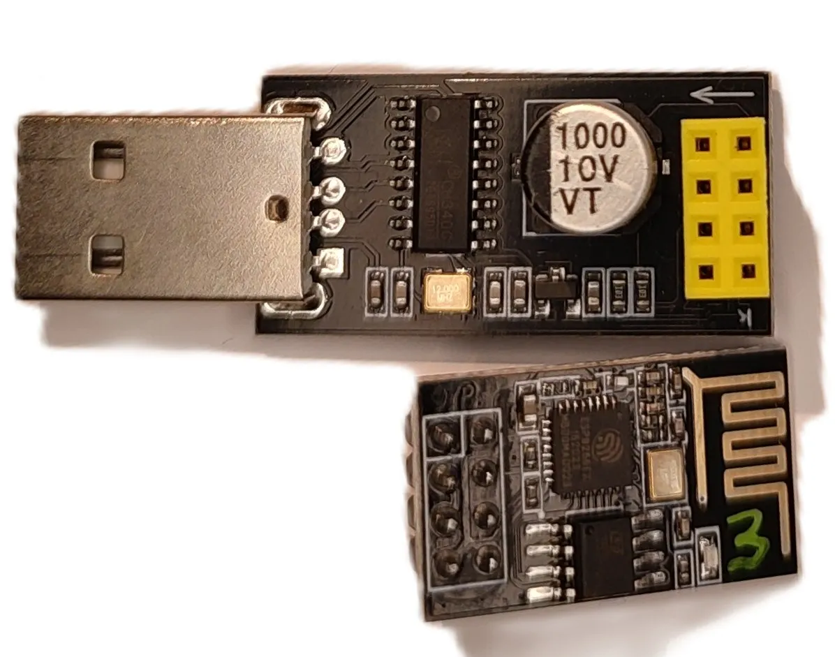
Note on this adapter - it requires GPIO0 (IO0) to be set to ground before plugging it in to enter boot mode. I got them with modules, but I have a separate programmer.